Time to play!
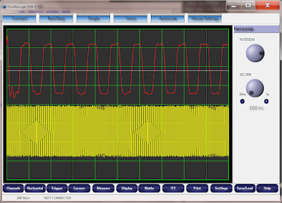
I'm still sampling at 100 MHz! the input signal is a 10 MHz square wave.
CH1 shows the actual square wave, while CH2 at moment shows the FPGA raw buffer.
I'm using the sinc(x) interpolation to rebuild the original wave form, and I've learnt 2 things.
1. From a spectrum point of view the beginning of the raw data is seen as a step gradient, which goes against the hypothesis of the Shannon theorem. That explain the first "distortion" of the CH1.
So it's easy to fix.
2. Now the second point is that the square wave is a little wavelike on the top and bottom... that I guess is because I haven't fixed the problem of the floor noise completely yet!
Therefore I'm going to work on that now.
1. by fixing the noise floor I think the square wave will look even better.
2. I could further improve the waveform by play with the delay in the DLL, so I could create an equivalent sample of 1 GSPS and therefore the waveform should look very squared. ( Now I understand why so many USB oscilloscope use the ETS)
Any suggestion is welcome.

No comments:
Post a Comment